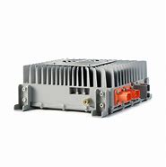
U1 is TL3842 pulse width modulation IC. Its 5 feet for the negative power supply, 7 feet for the positive power supply, 6 feet for the pulse output direct drive field effect tube Q1 (K1358) 3 feet for the maximum current limit, adjust the resistance of R25 (2.5 ohms) can adjust the maximum current of the charger.
Pin 2 is the voltage feedback. You can adjust the output voltage of the charger. 4 pin external oscillation resistor R1, and oscillation capacitor C1. T1 is a high-frequency pulse transformer. Its role has three.
The first is to step down the high voltage pulse to the low voltage pulse.
The second is to play the role of isolation of high voltage to prevent electric shock.
D4 is a high-frequency rectifier (16A60V) C10 is a low-voltage filter capacitor, D5 is a 12V regulator diode, U3 (TL431) is a precision reference voltage source, with U2 (optocoupler 4N35) to automatically adjust the role of the charger voltage. D10 is the power indicator, and D6 is the charging indicator.
R27 is the current sampling resistor (0.1 ohms, 5w) to change the resistance of W1 and can adjust the charger to the inflection point of the floating charge current (200-300 mA) when the power starts. There is about 300v on C11. This voltage is loaded to Q1 via T1.
The second way through R5, C8, C3, reach U1 pin 7. U1's pin 6 outputs a square wave pulse, Q1 works, and the current goes to the ground via R25. The voltage of T1 output coil is rectified and filtered by D4 and C10 to get a stable voltage. The voltage of T1 output coil is rectified and filtered by D4 and C10 to get a stable voltage. This voltage is charged to the battery by D7 (D7 plays the role of preventing the backflow of current from the battery to the charger).
D9 provides the reference voltage for LM358, which is divided by R26 and R4 to reach the second and fifth pin of LM358. During normal charging, there is a voltage of about 0.15-0.18V on R27, which is added to the third pin of LM358 by R17, and a high voltage is sent from pin 1. This voltage all the way through R18, forcing Q2 on.
D6 (red light) lights up, the second way into the LM358 pin 6, pin 7 output low voltage, forcing Q3 off, D10 (green light) off, and the charger into the constant current charging stage. When the battery voltage rises to about 44.2V, the charger enters the constant voltage charging stage, the output voltage is maintained at about 44.2V, the charger enters the constant voltage charging stage, and the current gradually decreases. When the charging current decreases to 200mA-300mA, the voltage at the top of R27 drops, the voltage at pin 3 of LM358 is lower than pin 2, pin 1 output low voltage, Q2 turns off, and D6 turns off. At the same time, pin 7 outputs a high voltage, this voltage makes Q3 conductive, D10 lit. The other way through D8, W1 to reach the feedback circuit so that the voltage is reduced. The charger enters the trickle charge stage. 1-2 hours later, the charge is finished.

Next:What to pay attention to in the installation of electric car controller
Previous:Intelligent charger common failures and repair methods
Contact Person: Miss. Kiki
| WhatsApp : | +8617763224709 |
|---|---|
| Skype : | +8617763224709 |
| WeChat : | +8617763224709 |
| Email : | kiki@lifepo4-battery.com |